
Juniper MX204 Trio ASIC, 100G and breakout ports
In this note, I’m going to talk about the Juniper MX204 router, and more specifically, the port combinations you can have and the associated configuration required. When you have flexible systems, that can support multiple port speeds, it’s a good practice to understand the limitations and the inner details (ASIC type and high level specs if available) to make sure it is correctly fitting your needs. If you have a way to test the devices with different combinations and under stress / loads, it’s even better, but not everybody can afford or rent traffic generators like Ixia or Spirent. Note that interesting projects are emerging, like Trex. Never had the opportunity to try it out, hopefully I could get some decent server hardware soon…
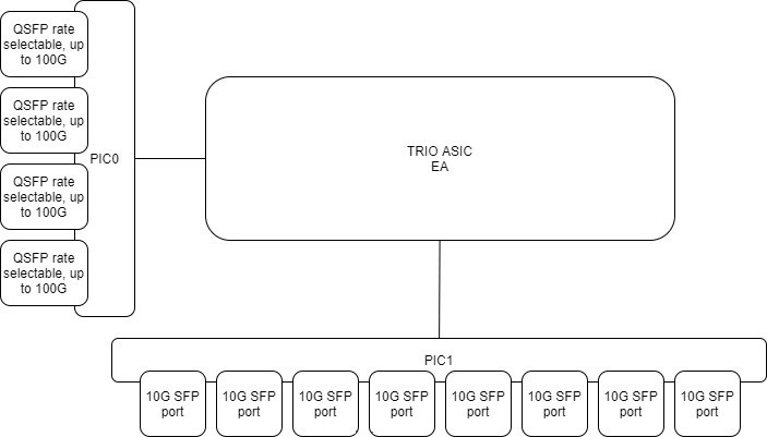
That’s being said, MX204 platform is a fixed 1-Rack Unit single RE MX router. It is based upon a single Juniper Trio GEN3 EA chipset supporting 400Gbps (or 480Gbps according to other sources). It is equipped of 4xQSFP28 rate selectable ports (4x1G/4x10G/40G/100G…) and 8-SFP+ ports(1G/10G). To start checking the feasibility to integrate this device in your design, you can leverage the port checker tool. It will give you the supported configurations and mix of ports, because you can’t have them all running at the same time :-)
While it looks the ASIC could support all the higher ports capacity all-together from a forwarding standpoint, when trying some port configurations in the port checker apps, it throws the following message
Not enough MACs left on asic EA-0
I’m not expert enough to tell where does it come from and to which intricacy it is linked to, but there are clearly some ASIC limitation here. So far I wasn’t able to find those details online, I’ll keep looking. If someone knows about it, I would be more than glad to learn! The easy guess would be: the system being capped at 400G, it needs to stay within that limit and thus cannot support all the combinations (those going above 400Gbps).
You can validate what is inside the box with:
user@mx204> show chassis hardware
Hardware inventory:
Item             Version  Part number  Serial number     Description
Chassis                                00000             JNP204 [MX204]
Routing Engine 0          BUILTIN      BUILTIN           RE-S-1600x8
CB 0             REV 38   750-069579   00000000          JNP204 [MX204]
FPC 0                     BUILTIN      BUILTIN           MPC
  PIC 0                   BUILTIN      BUILTIN           4XQSFP28 PIC
    Xcvr 0                NON-JNPR     000000000         QSFP28-100G-CU3M
    Xcvr 1                NON-JNPR     000000000         QSFP28-100G-CU3M
  PIC 1                   BUILTIN      BUILTIN           8XSFPP PIC
    Xcvr 0       1310nm   740-021309   0000000           SFP+-10G-LR
    Xcvr 1       1310nm   740-021309   0000000           SFP+-10G-LR
    Xcvr 2       1310nm   740-021309   0000000           SFP+-10G-LR
    Xcvr 3       1310nm   740-021309   0000000           SFP+-10G-LR
    Xcvr 4       1310nm   740-021309   0000000           SFP+-10G-LR
    Xcvr 5       1310nm   740-021309   0000000           SFP+-10G-LR
    Xcvr 6       1310nm   740-021309   0000000           SFP+-10G-LR
PEM 0            REV 04   740-070749   00000000000       JPSU-650W-AC-AO
PEM 1            REV 04   740-070749   00000000000       JPSU-650W-AC-AO
Fan Tray 0                                               Fan Tray, Front to Back Airflow - AFO
Fan Tray 1                                               Fan Tray, Front to Back Airflow - AFO
Fan Tray 2                                               Fan Tray, Front to Back Airflow - AFO
Two things:
- Flexible PIC/Port Concentrators (FPCs): is the general name of the entity that aggregates/connects port cards, oversimplistically, it basically provides “packet forwarding”
- Physical Interface Cards (PICs): provides interfaces / connectivity (pushing packets onto the wires)
First, you have to choose whether you use the PIC-mode or port-mode profiles. In a nutshell:
- pic mode: configure the same speed across the whole ASIC / FPC
- port mode: allow a mix of speeds
Both modes come with limitations:
- pic mode: straightforward but obviously, less flexible,
- port mode: flexible allow more granular settings
To perform a modification on the type, first, you need to shutdown the ASIC. This is impactful, so you need to do this either in an appropriate maintenance window or during staging.
Check FPC status
user@mx204> show chassis fpc 0
                     Temp  CPU Utilization (%)   CPU Utilization (%)  Memory    Utilization (%)
Slot State            (C)  Total  Interrupt      1min   5min   15min  DRAM (MB) Heap     Buffer
  0  Online           N/A     10          0       11     11     11    3136        8          8

user@mx204> show chassis fpc pic-status
Slot 0   Online       MPC
  PIC 0  Online       4XQSFP28 PIC
  PIC 1  Online       8XSFPP PIC
You can check PIC, detailed information:
user@mx204> show chassis pic pic-slot 0 fpc-slot 0
FPC slot 0, PIC slot 0 information:
  Type                             4XQSFP28 PIC
  State                            Online
  PIC version                  0.0
  Uptime			 4 days, 3 hours, 32 minutes, 3 seconds

PIC port information:
                         Fiber                    Xcvr vendor       Wave-    Xcvr         JNPR
  Port Cable type        type  Xcvr vendor        part number       length   Firmware     Rev
  1    100GBASE CU 3M    n/a   <VENDOR>           <CODE>            n/a      0.0


Port speed information:

  Port  PFE      Capable Port Speeds
  0      0       4x10GE, 40GE, 100GE
  1      0       4x10GE, 40GE, 100GE
  2      0       4x10GE, 40GE, 100GE
  3      0       4x10GE, 40GE, 100GE

user@mx204> show chassis pic pic-slot 1 fpc-slot 0
FPC slot 0, PIC slot 1 information:
  Type                             8XSFPP PIC
  State                            Online
  PIC version                  0.0
  Uptime			 4 days, 3 hours, 32 minutes, 8 seconds

PIC port information:
                         Fiber                    Xcvr vendor       Wave-    Xcvr         JNPR
  Port Cable type        type  Xcvr vendor        part number       length   Firmware     Rev
  0    GIGE 1000LX10     SM    <VENDOR>          S.1312.10.D       1310 nm  0.0
  1    10GBASE LR        SM    <VENDOR>          P.1396.10         1310 nm  0.0          1310nm
  2    10GBASE LR        SM    <VENDOR>          P.1396.10         1310 nm  0.0          1310nm
  3    10GBASE LR        SM    <VENDOR>          P.1396.10         1310 nm  0.0          1310nm
  4    10GBASE LR        SM    <VENDOR>          P.1396.10         1310 nm  0.0          1310nm
  5    10GBASE LR        SM    <VENDOR>          P.1396.10         1310 nm  0.0          1310nm
  6    10GBASE LR        SM    <VENDOR>          P.1396.10         1310 nm  0.0          1310nm
  7    10GBASE LR        SM    <VENDOR>          P.1396.10         1310 nm  0.0          1310nm
Then stop the PIC, the one interesting you:
user@mx204> request chassis pic pic-slot 0 fpc-slot 0 offline
user@mx204> request chassis pic pic-slot 1 fpc-slot 0 offline

user@mx204> show chassis fpc pic-status
Slot 0   Online       MPC
  PIC 0  Offline      4XQSFP28 PIC
  PIC 1  Offline      8XSFPP PIC
Modify the configuration (for example, like below). In port-mode, you need to set all the ports’ speeds.
user@mx204# show | compare
[edit]
+  chassis {
+      fpc 0 {
+          pic 0 {
+              port 0 {
+                  speed 100g;
+              }
+              port 1 {
+                  speed 100g;
+              }
+              port 2 {
+                  speed 40g;
+              }
+              port 3 {
+                  speed 40g;
+              }
+          }
+          pic 1 {
+              port 0 {
+                  speed 10g;
+              }
+              port 1 {
+                  speed 10g;
+              }
+              port 2 {
+                  speed 10g;
+              }
+              port 3 {
+                  speed 10g;
+              }
+              port 4 {
+                  speed 10g;
+              }
+              port 5 {
+                  speed 10g;
+              }
+              port 6 {
+                  speed 10g;
+              }
+              port 7 {
+                  speed 10g;
+              }
+          }
+      }
+  }
Then bring back online the PICs, it will take a few seconds to load up and then a couple more seconds (10-30sec) to get the ports up and running. It depends on the case, and Juniper JTAC said that the impact can be up to 5 minutes :-)
user@mx204> request chassis pic pic-slot 0 fpc-slot 0 online
fpc 0 pic 0 online initiated, use "show chassis fpc pic-status" to verify

user@mx204> request chassis pic pic-slot 1 fpc-slot 0 online
fpc 0 pic 1 online initiated, use "show chassis fpc pic-status" to verify

user@mx204> show chassis fpc pic-status
Slot 0   Online       MPC
  PIC 0  Online       4XQSFP28 PIC
  PIC 1  Ready        8XSFPP PIC

user@mx204> show chassis fpc pic-status
Slot 0   Online       MPC
  PIC 0  Online       4XQSFP28 PIC
  PIC 1  Online       8XSFPP PIC
In case of error, you’ll get an error message like this:
user@mx204> request chassis pic pic-slot 0 fpc-slot 0 online
FPC 0 has invalid pic/port config, cannot online PIC 0 of FPC 0
Port numbering in 40G or 100G modes is:
0/0 => et-0/0/0
0/1 => et-0/0/1
0/2 => et-0/0/2
0/3 => et-0/0/3
To put the QSFP ports in 10G mode (4x10G), you need to apply the following configuration:
user@mx204> show configuration chassis fpc 0 pic 0
port 0 {
    speed 100g;
}
port 1 {
    speed 100g;
}
port 2 {
    speed 10g;
}
port 3 {
    speed 10g;
}
With the adequate QSFP, here’s what it looks like:
user@mx204> show chassis pic fpc-slot 0 pic-slot 0 | match 4X10
  2    4X10GBASE LR      SM    <VENDOR>          <CODE>        1310 nm  0.0          10G x4
  3    4X10GBASE LR      SM    <VENDOR>          <CODE>        1310 nm  0.0          10G x4
...snipped...
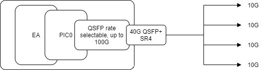
You can use a variety of breakout QSFP to 4xSFP DAC or AOC cables, or single transceivers 40G QSFP+ SR4 / PLR4 with breakout cables. The QSFP+ 40G PLR4 is a LR MPO/MTP cable, different from the QSFP+ 40G LR4 which is 40G over a single LC pair.
In that case, the port mapping is:
Example for port 0/0
xe-0/0/0:[0..3]
To deeper investigate ASIC related problems, note that you can request shell access to the PIC. Not sure it’s useful for everybody because some of these outputs needs advanced knowledge of the ASIC to take advantage of them. On the other hand, a few of them can be understood and could be useful when checking proper implementation of the configuration at ASIC level. Juniper ASICs are made of multiple sub-blocks (for some of them), this might be reflected at this shell level, that’s why you need to know a bit what is under the hood. I can only recommend this great read: Juniper MX Series, 2nd Edition
Remember, shell commands are not expected to be run in a ‘production’ environment. Generally, JTAC would advise what to do and which output to take. Please do it under their supervision or do it at your own risk!
user@mx204> start shell pfe network fpc0


SMPC platform (1601Mhz Intel(R) Atom(TM) CPU processor, 3136MB memory, 8192KB flash)

SMPC0(mx204 vty)#
SMPC0(mx204 vty)# show ea-asic
EA[0:0] Generic Configuration:
    PFE index:            0
    EA index:             0
    ASIC ID:              60
    ASIC number:          0
    ASIC name:            EA[0:0]
    JTAG ID:              00000000
    MQSS clock frequency: 863000000Hz
    LUSS clock frequency: 937500000Hz
    Major Version:        2
    Minor Version:        1
    Exists:               TRUE
    HW present:           TRUE
    Emulation mode:       FALSE
    HW Initialized:       TRUE
SMPC0(mx204 vty)# show jspec client

 ID       Name
  1       MPCS[0]
  2       XR2CHIP[0]
  3       XR2CHIP[1]
  4       EACHIP[0]
Note: you can also execute the commands ad-hoc using ‘request pfe execute command…’
We see in the above output that we have a single EA ASIC and two XR2 chips which are dedicated to lookups and queueing. In encourage you to read Day one: Inside the MX 5G for deeper dive information.
A few references:
- https://apps.juniper.net/home/port-checker/index.html
- https://www.juniper.net/us/en/local/pdf/whitepapers/2000331-en.pdf
- http://arnog.com.ar/presentaciones/me/4-juniper.pdf
- https://www.juniper.net/documentation/en_US/release-independent/junos/information-products/pathway-pages/mx-series/mx204/mx204-hw-guide.pdf
- https://www.oreilly.com/library/view/juniper-mx-series/9781491932711/
- https://www.oreilly.com/library/view/juniper-mx-series/9781449358143/ch01s04.html
- https://www.juniper.net/documentation/en_US/day-one-books/DO_MX5G.pdf