
JunOS: IS-IS routing (Intermediate System to Intermediate System)
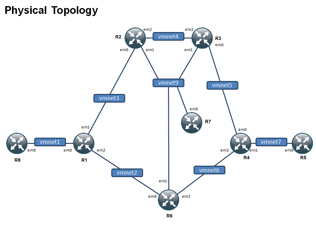
As I am currently working on Juniper SP courses, here is a home made topology that I will use to configure multiple technologies.
The first I want to introduce is the IS-IS routing protocol.
IS-IS is a routing protocol that use ISO addresses, thus whether it is for IPv4 or IPv6, the IS-IS configuration stays the same. Being IP agnostic is an appreciated feature in service providers backbones.
First, we need to configure the IPv4 addresses according to our diagram.
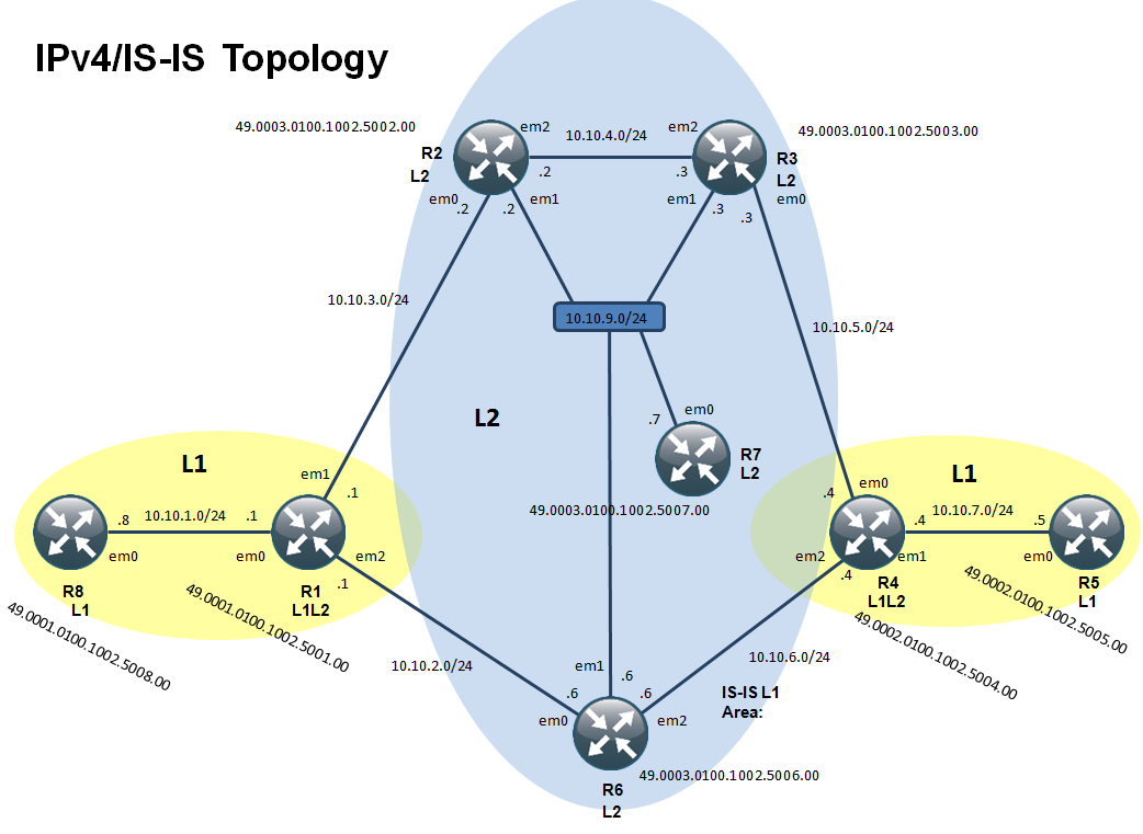
Once done, I configure the ISO addresses on each router. I enable this on the loopback 0 interface.
The ISO NET address is written in hexadecimal format and range form 8 to 20 bytes long.
They are built according to this rule:
– AFI, set to 49 (private ISO addressing), 1-byte
– Area ID, identifies the area in which the router is, 1-12-bytes
– System identifier, uniquely identifies the router (IS) like the OSPF route-id, 6-bytes
– Selector (NSEL), is a protocol identifier and needs to be set to 0, 1-byte
The best practice wants to derive the system ID from the loopback address.
R1 – 49.0001.0100.1002.5001.00
R8 – 49.0001.0100.1002.5008.00
R2 – 49.0003.0100.1002.5002.00
R3 – 49.0003.0100.1002.5003.00
R4 – 49.0002.0100.1002.5004.00
R5 – 49.0002.0100.1002.5005.00
R6 – 49.0003.0100.1002.5006.00
R7 – 49.0003.0100.1002.5007.00
root@JOSR1# show interfaces lo0
unit 0 {
    family inet {
        address 10.10.25.1/32;
    }
    family iso {
        address 49.0001.0100.1002.5001.00;
    }
}

root@JOSR2# show interfaces lo0
unit 0 {
    family inet {
        address 10.10.25.2/32;
    }
    family iso {
        address 49.0003.0100.1002.5002.00;
    }
}

root@JOSR3# show interfaces lo0
unit 0 {
    family inet {
        address 10.10.25.3/32;
    }
    family iso {
        address 49.0003.0100.1002.5003.00;
    }
}

root@JOSR4# show interfaces lo0
unit 0 {
    family inet {
        address 10.10.25.4/32;
    }
    family iso {
        address 49.0002.0100.1002.5004.00;
    }
}

root@JOSR5# show interfaces lo0
unit 0 {
    family inet {
        address 10.10.25.5/32;
    }
    family iso {
        address 49.0002.0100.1002.5005.00;
    }
}

root@JOSR6# show interfaces lo0
unit 0 {
    family inet {
        address 10.10.25.6/32;
    }
    family iso {
        address 49.0003.0100.1002.5006.00;
    }
}

root@JOSR7# show interfaces lo0
unit 0 {
    family inet {
        address 10.10.25.7/32;
    }
    family iso {
        address 49.0003.0100.1002.5007.00;
    }
}

root@JOSR8# show interfaces lo0
unit 0 {
    family inet {
        address 10.10.25.8/32;
    }
    family iso {
        address 49.0001.0100.1002.5008.00;
    }
}
Then I activate IS-IS routing protocol on the two L1 only routers R8 and R5.
interfaces {
    em0 {
        description to_R1;
        unit 0 {
            family inet {
                address 10.10.1.8/24;
            }
            family iso;
        }
    }
protocols {
    isis {
        level 2 disable;
        level 1 wide-metrics-only;
        interface em0.0;
        interface lo0.0;
    }
}
root@JOSR5# set interfaces em0 unit 0 family iso
root@JOSR5# set protocols isis level 2 disable
root@JOSR5# set protocols isis interface em0.0
root@JOSR5# set protocols isis interface lo0.0
root@JOSR5# set protocols isis level 1 wide-metrics-only
root@JOSR5# commit
Then I configure the two L1/L2 routers in their corresponding areas (R1 and R4)
Note that nothing is to be done to activate both levels, by default a JunOS router is set to L1/L2.
root@JOSR1# set interfaces em0.0 family iso
root@JOSR1# set interfaces em1.0 family iso
root@JOSR1# set interfaces em2.0 family iso
root@JOSR1# set protocols isis level 1 wide-metrics-only
root@JOSR1# set protocols isis level 2 wide-metrics-only
root@JOSR1# set protocols isis interface em0.0
root@JOSR1# set protocols isis interface em1.0
root@JOSR1# set protocols isis interface lo0.0
root@JOSR1# set protocols isis interface em2.0

root@JOSR1# run show isis adjacency
Interface             System         L State        Hold (secs) SNPA
em0.0                 JOSR8          1  Up                   21  0:c:29:fb:dd:c9
root@JOSR4# set interfaces em0.0 family iso
root@JOSR4# set interfaces em1.0 family iso
root@JOSR4# set interfaces em2.0 family iso
root@JOSR4# set protocols isis level 1 wide-metrics-only
root@JOSR4# set protocols isis level 2 wide-metrics-only
root@JOSR4# set protocols isis interface em0.0
root@JOSR4# set protocols isis interface em1.0
root@JOSR4# set protocols isis interface em2.0
root@JOSR4# set protocols isis interface lo0.0

root@JOSR4# run show isis interface
IS-IS interface database:
Interface             L CirID Level 1 DR        Level 2 DR        L1/L2 Metric
em0.0                 3   0x1 JOSR4.00          JOSR4.00               10/10
em1.0                 3   0x1 JOSR4.00          JOSR4.00               10/10
em2.0                 3   0x1 JOSR4.00          JOSR4.00               10/10
lo0.0                 0   0x1 Passive           Passive                 0/0

root@JOSR4# run show isis adjacency
Interface             System         L State        Hold (secs) SNPA
em1.0                 JOSR5          1  Up                   21  0:50:56:26:c1:b3
The last two commands, show isis adjacency and show isis interface are good to verify and troubleshoot simple connectivity issues at the IS-IS level.
At this stage we have our two L1 islands configured. Next step is to deploy the level 2 area that will interconnect the L1 areas.
The interface setup is exactly the same. Regarding the IS-IS routing configuration, we are going to disable the level 1.
set protocols isis level 1 disable
set protocols isis level 2 wide-metrics-only
As you can see, I added the wide-metrics-only keyword as I think it is a best practice to just use a single scalable metric set.
The adjancencies were properly formed as L2 only
root@JOSR6# run show isis adjacency
Interface             System         L State        Hold (secs) SNPA
em0.0                 JOSR1          2  Up                   21  0:50:56:32:d6:ef
em1.0                 JOSR2          2  Up                    7  0:50:56:28:66:eb
em1.0                 JOSR3          2  Up                   26  0:c:29:34:76:78
em1.0                 JOSR7          2  Up                   18  0:50:56:23:a4:5f
em2.0                 JOSR4          2  Up                   26  0:50:56:29:bd:5f

root@JOSR6# run show isis interface
IS-IS interface database:
Interface             L CirID Level 1 DR        Level 2 DR        L1/L2 Metric
em0.0                 2   0x2 Disabled          JOSR6.02               10/10
em1.0                 2   0x1 Disabled          JOSR2.02               10/10
em2.0                 2   0x3 Disabled          JOSR6.03               10/10
lo0.0                 0   0x1 Passive           Passive                 0/0
Now let’s observe route propagation.
On R8 we receive all R1 prefixes, because they are on the same level (level1). All other prefixes, for example loopback from R2 or R6 are not seen.
root@JOSR8# run show route protocol isis

inet.0: 7 destinations, 7 routes (7 active, 0 holddown, 0 hidden)
+ = Active Route, - = Last Active, * = Both

0.0.0.0/0          *[IS-IS/15] 00:06:36, metric 10
                    > to 10.10.1.1 via em0.0
10.10.2.0/24       *[IS-IS/15] 00:26:10, metric 20
                    > to 10.10.1.1 via em0.0
10.10.3.0/24       *[IS-IS/15] 00:26:10, metric 20
                    > to 10.10.1.1 via em0.0
10.10.25.1/32      *[IS-IS/15] 00:26:10, metric 10
                    > to 10.10.1.1 via em0.0

iso.0: 1 destinations, 1 routes (1 active, 0 holddown, 0 hidden)
What is interesting in the previous output is that you can see a default route learned from [IS-IS].
This local default route is, in fact, generated by IS-IS. It is used to exit the level 1 zone because of the presence of L1/L2 router.
root@JOSR8# run show isis database
IS-IS level 1 link-state database:
LSP ID                      Sequence Checksum Lifetime Attributes
JOSR1.00-00                      0x5   0x74b4     1091 L1 L2 Attached
JOSR1.02-00                      0x3   0x890e      821 L1 L2
JOSR8.00-00                      0x5   0xc9c0      612 L1
  3 LSPs

IS-IS level 2 link-state database:
  0 LSPs
Ping works effectively:
root@JOSR8# run show route 10.10.25.2

inet.0: 7 destinations, 7 routes (7 active, 0 holddown, 0 hidden)
+ = Active Route, - = Last Active, * = Both

0.0.0.0/0          *[IS-IS/15] 00:07:03, metric 10
                    > to 10.10.1.1 via em0.0

root@JOSR8# run ping 10.10.25.2
PING 10.10.25.2 (10.10.25.2): 56 data bytes
64 bytes from 10.10.25.2: icmp_seq=0 ttl=63 time=0.367 ms
64 bytes from 10.10.25.2: icmp_seq=1 ttl=63 time=0.340 ms
64 bytes from 10.10.25.2: icmp_seq=2 ttl=63 time=0.388 ms
^C
--- 10.10.25.2 ping statistics ---
3 packets transmitted, 3 packets received, 0% packet loss
round-trip min/avg/max/stddev = 0.340/0.365/0.388/0.020 ms
In the level 2, the routers have the full view of the routing table, for example on R2:
root@JOSR2# run show route protocol isis

inet.0: 19 destinations, 19 routes (19 active, 0 holddown, 0 hidden)
+ = Active Route, - = Last Active, * = Both

10.10.1.0/24       *[IS-IS/18] 00:18:05, metric 20
                    > to 10.10.3.1 via em0.0
10.10.2.0/24       *[IS-IS/18] 00:17:35, metric 20
                    > to 10.10.3.1 via em0.0
                      to 10.10.9.6 via em1.0
10.10.5.0/24       *[IS-IS/18] 00:17:20, metric 20
                      to 10.10.9.3 via em1.0
                    > to 10.10.4.3 via em2.0
10.10.6.0/24       *[IS-IS/18] 00:17:35, metric 20
                    > to 10.10.9.6 via em1.0
10.10.7.0/24       *[IS-IS/18] 00:17:10, metric 30
                    > to 10.10.9.3 via em1.0
                      to 10.10.9.6 via em1.0
                      to 10.10.4.3 via em2.0
10.10.25.1/32      *[IS-IS/18] 00:18:05, metric 10
                    > to 10.10.3.1 via em0.0
10.10.25.3/32      *[IS-IS/18] 00:17:20, metric 10
                    > to 10.10.9.3 via em1.0
                      to 10.10.4.3 via em2.0
10.10.25.4/32      *[IS-IS/18] 00:17:10, metric 20
                      to 10.10.9.3 via em1.0
                      to 10.10.9.6 via em1.0
                    > to 10.10.4.3 via em2.0
10.10.25.5/32      *[IS-IS/18] 00:17:10, metric 30
                      to 10.10.9.3 via em1.0
                      to 10.10.9.6 via em1.0
                    > to 10.10.4.3 via em2.0
10.10.25.6/32      *[IS-IS/18] 00:17:35, metric 10
                    > to 10.10.9.6 via em1.0
10.10.25.7/32      *[IS-IS/18] 00:17:29, metric 10
                    > to 10.10.9.7 via em1.0
10.10.25.8/32      *[IS-IS/18] 00:18:05, metric 20
                    > to 10.10.3.1 via em0.0

iso.0: 1 destinations, 1 routes (1 active, 0 holddown, 0 hidden)
Because the level 1 areas have a default route and the level 2 area has the full view, full connectivity is achieved in this network.
We can test a ping from R5 (area 49.0002) to R8 (area 49.0001):
[edit]
root@JOSR5# run ping 10.10.25.8
PING 10.10.25.8 (10.10.25.8): 56 data bytes
64 bytes from 10.10.25.8: icmp_seq=0 ttl=61 time=0.775 ms
64 bytes from 10.10.25.8: icmp_seq=1 ttl=61 time=1.038 ms
^C
--- 10.10.25.8 ping statistics ---
2 packets transmitted, 2 packets received, 0% packet loss
round-trip min/avg/max/stddev = 0.775/0.907/1.038/0.132 ms

[edit]
root@JOSR5# run traceroute 10.10.25.8
traceroute to 10.10.25.8 (10.10.25.8), 30 hops max, 40 byte packets
 1  10.10.7.4 (10.10.7.4)  0.231 ms  0.135 ms  0.093 ms
 2  10.10.6.6 (10.10.6.6)  0.255 ms  0.163 ms  0.134 ms
 3  10.10.2.1 (10.10.2.1)  0.282 ms  0.209 ms  0.203 ms
 4  10.10.25.8 (10.10.25.8)  0.364 ms  0.332 ms  0.369 ms
It works, the next article will deal with route leaking.
You can find more information on IS-IS (much more details!) in the following article from INETZERO: https://inetzero.com/isis-training-and-junos-configuratio/