
DMVPN Phase 3: network optimization
DMVPN phase 3 improves architecture designs and scaling possibilities by allowing direct spoke to spoke connection. Previously on phase 2 this was enabled but needed to go through the hub due to the basic NHRP process. Phase 3 also allows route summarization, which is, in large DMVPN networks improves the routing protocol setup and lower the table sizes on the branch routers.
Hub configuration:
interface Tunnel0
 ip nhrp redirect
Spoke configurations:
interface Tunnel0
 ip nhrp shortcut
Then modify EIGRP back to its default settings for next-hop.
router eigrp bluevpn
 address-family ipv4 unicast autonomous-system 150
  af-interface Tunnel0
  next-hop-self
I added the following loopbacks to see summarization purpose.
R6#
interface Loopback2
 ip address 10.10.6.1 255.255.255.0

router eigrp 150
 network 10.10.6.0 0.0.0.255

R7#
interface Loopback2
 ip address 10.10.7.1 255.255.255.0

router eigrp 150
 network 10.10.7.0 0.0.0.255

R8#
interface Loopback2
 ip address 10.10.8.1 255.255.255.0

router eigrp 150
 network 10.10.8.0 0.0.0.255
Check the RT on R6
router eigrp 150
 network 10.10.8.0 0.0.0.255

R6#sh ip ro

     10.0.0.0/8 is variably subnetted, 2 subnets, 2 masks
C       10.10.6.0/24 is directly connected, Loopback2
D       10.0.0.0/8 [90/14336000] via 192.168.1.1, 00:33:26, Tunnel0


R6#sh ip ro 10.10.8.1
Routing entry for 10.0.0.0/8
  Known via "eigrp 150", distance 90, metric 14336000, type internal
  Redistributing via eigrp 150
  Last update from 192.168.1.1 on Tunnel0, 00:34:47 ago
  Routing Descriptor Blocks:
  * 192.168.1.1, from 192.168.1.1, 00:34:47 ago, via Tunnel0
      Route metric is 14336000, traffic share count is 1
      Total delay is 555000 microseconds, minimum bandwidth is 20000 Kbit
      Reliability 255/255, minimum MTU 1400 bytes
      Loading 1/255, Hops 1
Then if we look at the NHRP resolution and traffic flow now, we can see that the traditional NHRP request / reply process is happening as in phase 2, however this time an NHRP traffic indication message is passed to both spokes from the hub. Those packets are highlighted is blue in the capture below. Those indications packets contain a field that is used by each routers to populate their NHRP cache.
More details is found on cisco.com http://www.cisco.com/c/en/us/td/docs/ios/12_4t/12_4t11/ht_nhrp.html#wp1060829
NHRP SENDS A RESOLUTION REQUEST FOR A SHORTCUT PATH AFTER RECEIVING AN NHRP REDIRECT TRAFFIC INDICATION MESSAGE. AN NHRP REDIRECT TRAFFIC INDICATION IS GENERATED BY AN INTERMEDIATE NODE WHEN A DATA PACKET IS FORWARDED WITHIN THE SAME DMVPN NETWORK (IN AND OUT THE SAME TUNNEL INTERFACE). THE REDIRECT IS SENT TO THE PREVIOUS TUNNEL HOP (SPOKE) ON THE TUNNEL FROM WHICH THE DATA PACKET WAS RECEIVED. LIKE AN INTERNET CONTROL MESSAGE PROTOCOL (ICMP) MESSAGE, THE NHRP REDIRECT MESSAGE INCLUDES THE IP HEADER AND THE FIRST EIGHT DATA BYTES OF THE DATA PACKET THAT TRIGGERS THE REDIRECT. THIS INFORMATION IS USED BY NHRP ON THE PREVIOUS TUNNEL HOP TO DETERMINE WHETHER AND WHERE TO SEND A RESOLUTION REQUEST. THAT IS, NHRP WOULD MATCH AGAINST THE INTEREST LIST CONFIGURATION TO DETERMINE WHETHER TO SEND A RESOLUTION REQUEST.
THE NHRP REDIRECT TRAFFIC INDICATION IS GENERATED FOR EACH UNIQUE COMBINATION OF SOURCE-NBMA IP ADDRESS (PREVIOUS TUNNEL HOP) AND DATA PACKET (DESTINATION IP ADDRESS); THAT IS, REDIRECT IS GENERATED INDEPENDENT OF THE SOURCE IP ADDRESS OF THE DATA PACKET. IT PURELY DEPENDS ON THE DESTINATION IP ADDRESS AND THE SOURCE-NBMA ADDRESS OF THE INCOMING GENERIC ROUTING ENCAPSULATION (GRE) ENCAPSULATED DATA PACKET. THESE NHRP REDIRECT MESSAGES ARE RATE-LIMITED. A CONFIGURABLE OPTION IS PROVIDED TO DETERMINE THE RATE AT WHICH NHRP REDIRECTS WILL BE GENERATED FOR THE SAME COMBINATION OF SOURCE-NBMA ADDRESS AND DATA DESTINATION IP ADDRESS.
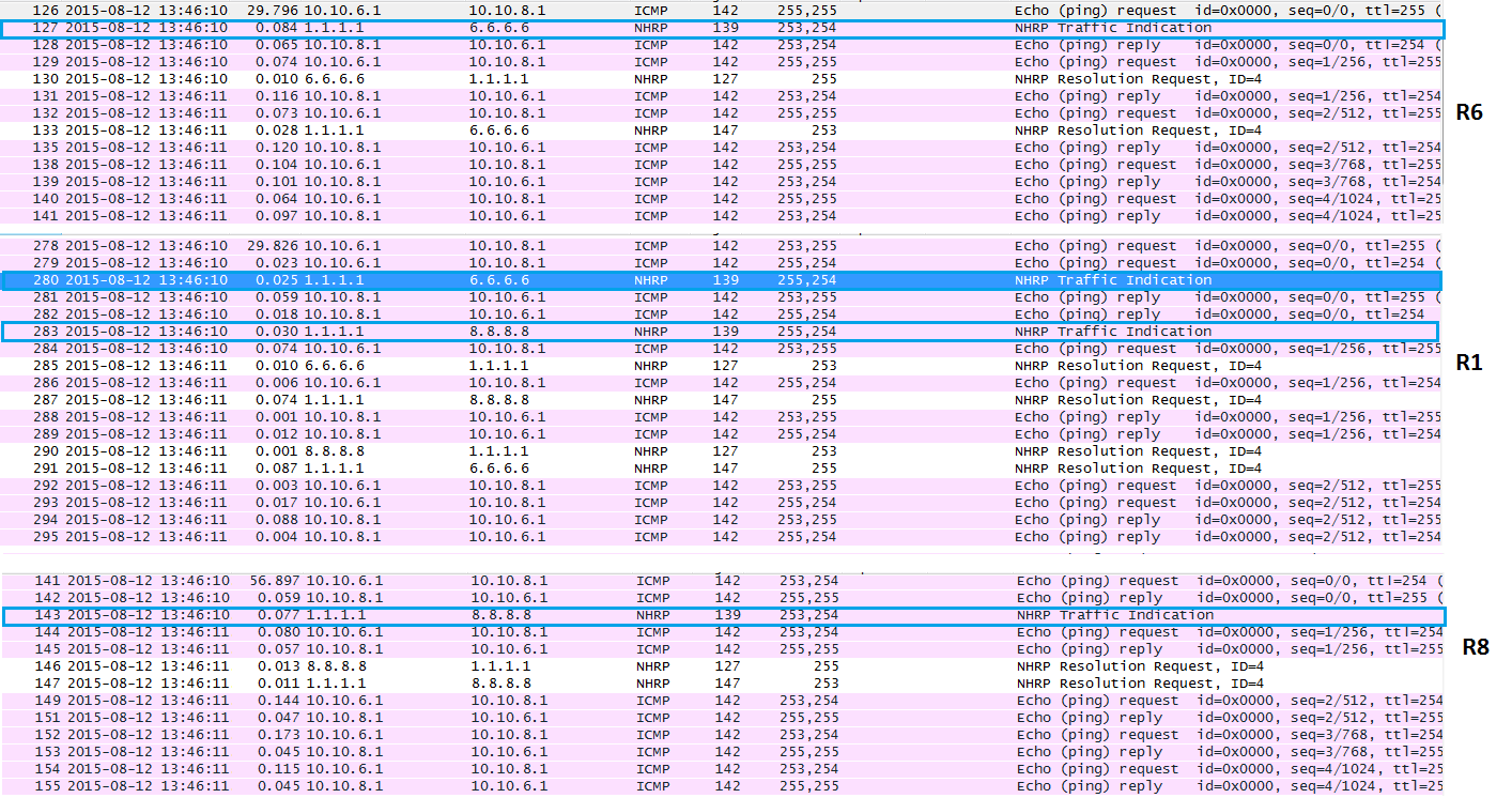
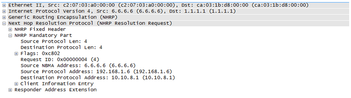
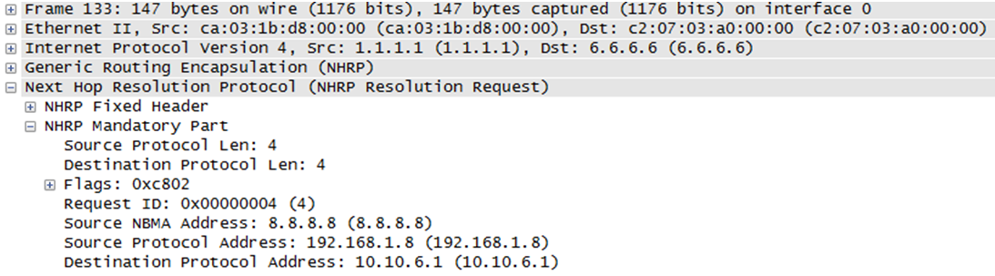
Once this process happens we can observe different requests:
R6 requesting R1 for destination 10.10.8.1
R1 responding to R6 stating R8 information
Once the NHRP cache is populated, no more pings are seen on R1.
Prefixes are well resolved despite the unique summary in the routing table.
Traceroute shows only one hop as expected with spoke to spoke communication.
R6#sh ip nhrp
10.10.6.0/24 via 192.168.1.6, Tunnel0 created 00:09:20, expire 01:50:41
  Type: dynamic, Flags: router unique local
  NBMA address: 6.6.6.6
    (no-socket)
10.10.8.0/24 via 192.168.1.8, Tunnel0 created 00:09:18, expire 01:50:41
  Type: dynamic, Flags: router
  NBMA address: 8.8.8.8

R6#traceroute 10.10.8.1 so lo2

Type escape sequence to abort.
Tracing the route to 10.10.8.1

  1 192.168.1.8 124 msec 140 msec 140 msec
NHRP aslo altered the routing table to push routes with the corrected next-hop, this is another example from R6
R6# ping 10.10.8.1 source lo2 rep 10
Type escape sequence to abort.
Sending 10, 100-byte ICMP Echos to 10.10.8.1, timeout is 2 seconds:
Packet sent with a source address of 10.10.6.1
!!!!!!!!!!

R6#traceroute 10.10.8.1 source lo2
Type escape sequence to abort.
Tracing the route to 10.10.8.1
VRF info: (vrf in name/id, vrf out name/id)
  1 192.168.1.8 50 msec *  38 msec
Routing table excerpt:
H        10.10.8.0/24 [250/1] via 192.168.1.8, 00:00:09, Tunnel0

H        192.168.1.8/32 is directly connected, 00:00:09, Tunnel0
The route is know via NHRP (H) and has the correct next-hop (spoke). Normally, the spoke has only the global route announced by the hub (10/8).
R6#sh ip ro 10.10.8.0
Routing entry for 10.10.8.0/24
  Known via "nhrp", distance 250, metric 1
  Last update from 192.168.1.8 on Tunnel0, 00:00:57 ago
  Routing Descriptor Blocks:
  * 192.168.1.8, from 192.168.1.8, 00:00:57 ago, via Tunnel0
      Route metric is 1, traffic share count is 1
      MPLS label: none