
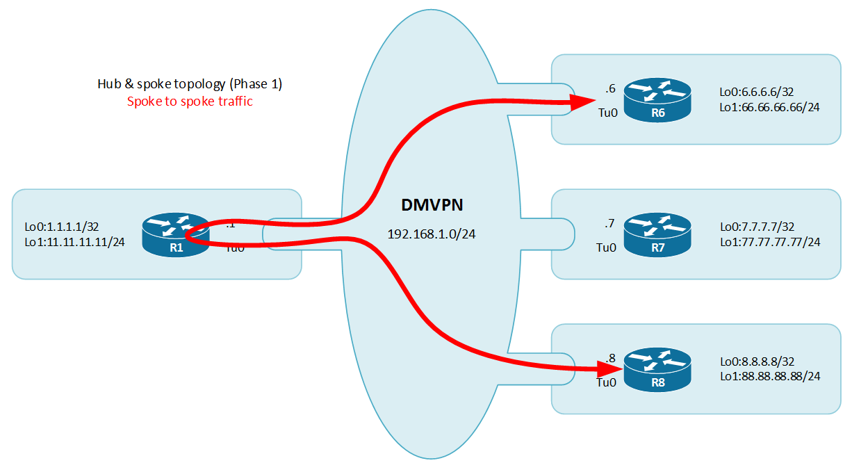
DMVPN Phase 1: Hub and Spoke
This article stands as an introduction to DMVPN with a DMVPN Phase 1 lab.
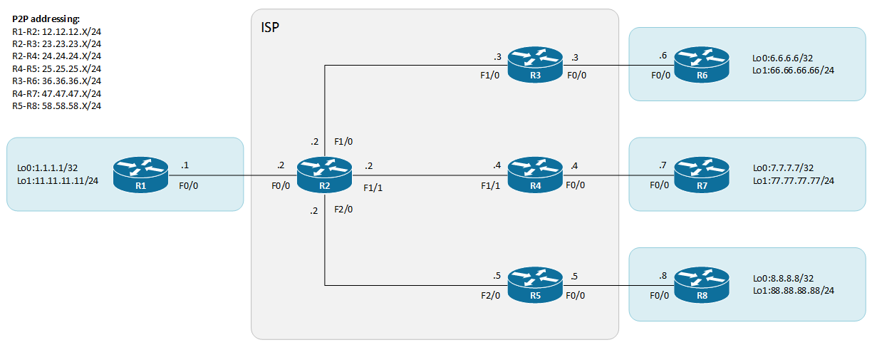
The topology is composed of a service provider network R2, R3, R4 and R5.
They exchange routes with internal BGP AS 20 and the sites network are advertised statically and then redistributed in BGP. R2 is a route-reflector that allows for proper route propagation across all customer equipment (CE).
The customer devices are R1, R6, R7 and R8. R2 is the hub router in the coming DMVPN network and R6, R7 and R8 are spokes. R1 is located in the head office and the three others are branch sites.
BGP configuration:
R2#sh ip bgp summary

Neighbor        V           AS MsgRcvd MsgSent   TblVer  InQ OutQ Up/Down  State/PfxRcd
23.23.23.3      4           20      40      46       14    0    0 00:32:20        3
24.24.24.4      4           20      40      46       14    0    0 00:32:18        3
25.25.25.5      4           20      40      46       14    0    0 00:32:18        3

R2#sh run | s router bgp
router bgp 20
 bgp log-neighbor-changes
 redistribute connected
 redistribute static
 neighbor PG peer-group
 neighbor PG remote-as 20
 neighbor PG route-reflector-client
 neighbor PG send-community both
 neighbor 23.23.23.3 peer-group PG
 neighbor 24.24.24.4 peer-group PG
 neighbor 25.25.25.5 peer-group PG
R4#sh run

!
router bgp 20
 bgp log-neighbor-changes
 redistribute connected
 redistribute static
 neighbor 24.24.24.2 remote-as 20
!

!
ip route 7.7.7.7 255.255.255.255 47.47.47.7
This topology will remain for the next 3 cases covered.
The first DMVPN example will be a Phase 1 DMVPN. In the phase 1 the behavior is hub and spoke. The hub tunnel is in mGRE mode which allows for dynamic establishment of the point to point tunnel defined on the spokes. In this first example no IPsec will be implemented tunnels will remain unprotected using GRE encapsulation (RFC1701).
First let’s configure the hub router, R1
Define a loopback address to source the tunnel :
interface Loopback0
 ip address 1.1.1.1 255.255.255.255
Then configure the tunnel interface.
interface Tunnel0
 bandwidth 100000 # Reflect bandwidth of the tunnel, can be useful for EIGRP and QoS
 ip address 192.168.1.1 255.255.255.0
 no ip redirects
 ip mtu 1400 # Recommended MTU settings
 ip nhrp authentication cisco # Authentication for NHRP exchange
 ip nhrp map multicast dynamic # Used to populate the NHRP database listening to the multicast traffic from the clients, thus eliminate static configurations.
 ip nhrp network-id 1 # Identify the DMVPN cloud
 ip nhrp server-only # There is a single hub, it will be server only
 ip tcp adjust-mss 1360 # Recommended MSS settings
 tunnel source Loopback0 # Tunnel source
 tunnel mode gre multipoint # Tunnel mode set to mGRE
 tunnel key 123 # Tunnel key to identify the mGRE tunnel if multiple mGRE instances are sourced with the same loopback. Not a requirement anymore.
NHRP (Next-Hop resolution Protocol) is defined in RFC2332. The Cisco implementation fully support the RFC and extends it. This protocol is useful in NBMA networks where it acts like ARP mapping an IP address to a NBMA layer IP address. NHRP allows Next-Hop Clients (NHC) to register dynamically to Next-Hop Servers (NHS). This phase called registration make it simple even with changing IP addresses and NAT. NHRP also allows spoke to spoke communication by resolving getting NBMA addresses of other spokes. This prevents going through the hub and uses its resources.
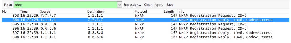
NHRP works based on the registration requests (NHC) and the registration replies (NHS).
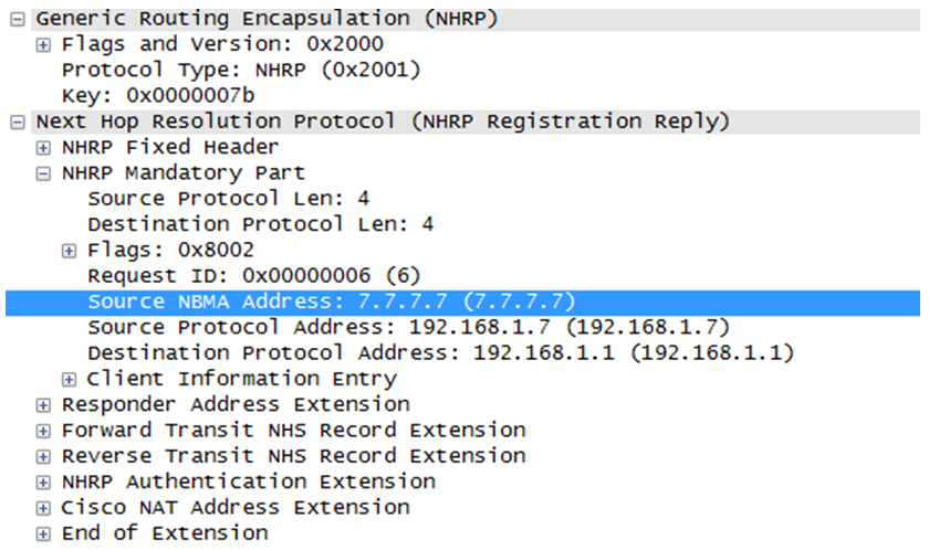
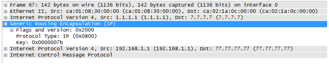
On the following capture, we can observe the GRE encapsulation provided for NHRP and the NHRP layer with the addresses (NBMA and protocol). We can also see the Cisco NAT extensions.
mGRE also known as multipoint GRE is a technology that provides dynamic tunneling. Basically GRE encapsulates in a point to point fashion, network layer packet into an IP tunnel adding a specific GRE header. That can be seen on the image below . mGRE is a similar protocol but instead of being point to point it provides a single termination endpoint on one side and authorize multiple other endpoints on the other side (dynamic tunnels). This allows for different tunnel patterns, if both hub and spokes are configured in that way they can establish hub and spoke and spoke to spoke sessions. We can also note that mGRE is not only used with NHRP in DMVPN set up but also in MPLS VPN over mGRE techniques http://www.cisco.com/c/en/us/td/docs/ios-xml/ios/interface/configuration/xe-3s/ir-xe-3s-book/ir-mpls-vpnomgre-xe.html%23GUID-D6F7FC63-F51C-4DBA-B76C-40181C9083D3.
Then the configuration must continue on the spoke routers to create the DMVPN cloud.
R6
interface Loopback0
 ip address 6.6.6.6 255.255.255.255
!
interface Tunnel0
 bandwidth 20000
 ip address 192.168.1.6 255.255.255.0
 ip mtu 1400
 ip authentication mode eigrp 150 md5
 ip authentication key-chain eigrp 150 EIGRP-KEYS
 ip nhrp authentication cisco
 ip nhrp map multicast 1.1.1.1 ## Multicast support for IGP
 ip nhrp map 192.168.1.1 1.1.1.1 ## Static mapping for the hub [overlay][NBMA]
 ip nhrp network-id 1
 ip nhrp nhs 192.168.1.1
 ip tcp adjust-mss 1360
 tunnel source Loopback0
 tunnel destination 1.1.1.1 ## Static tunnel destination
 tunnel key 123
R7
interface Loopback0
 ip address 7.7.7.7 255.255.255.255
!
interface Tunnel0
 ip address 192.168.1.7 255.255.255.0
 ip mtu 1400
 ip authentication mode eigrp 150 md5
 ip authentication key-chain eigrp 150 EIGRP-KEYS
 ip nhrp authentication cisco
 ip nhrp map multicast 1.1.1.1
 ip nhrp map 192.168.1.1 1.1.1.1
 ip nhrp network-id 1
 ip nhrp nhs 192.168.1.1
 ip tcp adjust-mss 1360
 tunnel source Loopback0
 tunnel destination 1.1.1.1
 tunnel key 123
R8
interface Loopback0
 ip address 8.8.8.8 255.255.255.255
!
interface Tunnel0
 ip address 192.168.1.8 255.255.255.0
 ip mtu 1400
 ip authentication mode eigrp 150 md5
 ip authentication key-chain eigrp 150 EIGRP-KEYS
 ip nhrp authentication cisco
 ip nhrp map multicast 1.1.1.1
 ip nhrp map 192.168.1.1 1.1.1.1
 ip nhrp network-id 1
 ip nhrp nhs 192.168.1.1
 ip tcp adjust-mss 1360
 tunnel source Loopback0
 tunnel destination 1.1.1.1
 tunnel key 123
Once this in place you can check the DMVPN and NHRP status with the following commands :
R1#  sh dmvpn
Legend: Attrb --> S - Static, D - Dynamic, I - Incomplete
        N - NATed, L - Local, X - No Socket
        # Ent --> Number of NHRP entries with same NBMA peer
        NHS Status: E --> Expecting Replies, R --> Responding, W --> Waiting
        UpDn Time --> Up or Down Time for a Tunnel
==========================================================================

Interface: Tunnel0, IPv4 NHRP Details
Type:Hub, NHRP Peers:3,

 # Ent  Peer NBMA Addr Peer Tunnel Add State  UpDn Tm Attrb
 ----- --------------- --------------- ----- -------- -----
     1         6.6.6.6     192.168.1.6    UP 01:37:51     D
     1         7.7.7.7     192.168.1.7    UP 01:37:48     D
     1         8.8.8.8     192.168.1.8    UP 01:37:48     D

R1#sh ip nhrp
192.168.1.6/32 via 192.168.1.6
   Tunnel0 created 01:39:42, expire 01:41:56
   Type: dynamic, Flags: unique registered
   NBMA address: 6.6.6.6
192.168.1.7/32 via 192.168.1.7
   Tunnel0 created 01:39:39, expire 01:41:46
   Type: dynamic, Flags: unique registered
   NBMA address: 7.7.7.7
192.168.1.8/32 via 192.168.1.8
   Tunnel0 created 01:39:38, expire 01:41:55
   Type: dynamic, Flags: unique registered
   NBMA address: 8.8.8.8

R1#show ip cef
Prefix               Next Hop             Interface

66.66.66.0/24        192.168.1.6          Tunnel0
77.77.77.0/24        192.168.1.7          Tunnel0
88.88.88.0/24        192.168.1.8          Tunnel0
R6#sh dmvpn
Legend: Attrb --> S - Static, D - Dynamic, I - Incompletea
        N - NATed, L - Local, X - No Socket
        # Ent --> Number of NHRP entries with same NBMA peer

Tunnel0, Type:Spoke, NHRP Peers:1,
 # Ent  Peer NBMA Addr Peer Tunnel Add State  UpDn Tm Attrb
 ----- --------------- --------------- ----- -------- -----
     1         1.1.1.1     192.168.1.1  NHRP   00:18:14 S
As you can see the “show dmvpn” give the nature of the tunnel: D for dynamic on the hub and S for static on the spoke (p2p GRE).
You have also access to debug commands in case of troubleshooting, they are quite helpful to uncover authentication or bad configurations. We will go through the troubleshooting later.
R6#debug nhrp ?
  cache      NHRP cache operations
  condition  NHRP conditional debugging
  error      NHRP errors
  extension  NHRP extension processing
  packet     NHRP activity
  rate       NHRP rate limiting


R6#debug dmvpn ?
  all        enable all level debugging
  condition  conditional debugging for enabled
  detail     detailed reports
  error      error reports
  packet     packet level debugging
Once the overlay infrastructure in place (the tunnels), routing must be set up so each site can discuss with each other. In the DMVPN phase 1 this communication will go through the hub, but we will later see that it is possible to directly establish spoke to spoke tunnels.
There are two recommended protocols for DMVPN clouds: EIGRP and BGP because of their distance-vector / path-vector nature. OSPF which is link state is not recommended as well as RIP which lacks of scalability and tune-ability. IS-IS which run on top of CLNS (OSI) is not supported.
In this example I will set up EIGRP (Enhanced Interior Gateway Routing Protocol) as routing protocol for the cloud network. There will be a dedicated named instance for the DMVPN cloud.
R1
key chain EIGRP-KEYS
 key 1
  key-string bluevpn
  accept-lifetime 00:00:00 Jan 1 1995 infinite
!
router eigrp bluevpn
 !
 address-family ipv4 unicast autonomous-system 150
  !
  af-interface Tunnel0
   summary-address 10.0.0.0 255.0.0.0
   summary-address 172.16.0.0 255.240.0.0
   summary-address 192.168.0.0 255.255.0.0
   authentication mode md5
   authentication key-chain EIGRP-KEYS
   no next-hop-self
   no split-horizon
  exit-af-interface
  !
  topology base
  exit-af-topology
  network 11.11.11.0 0.0.0.255
  network 192.168.1.0
 exit-address-family
!
In the present case I created a named EIGRP 64-bits instance (bluevpn), and then defined the AS 150. EIGRP will be set up on tunnel 0 interface and will send the RFC1918 summaries. Authentication is activated in MD5 mode and linked to key chain called EIGRP-KEYS. Next-hop information is preserved for spoke to spoke communication and split-horizon deactivated.
Split horizon is a feature that normally prevents routing loops by preventing to announce a subnet on the same interface it was received. However in an NBMA network this feature must be override because either you use multipoint tunnels or sub-interfaces the ingress and egress interface will be the same from a routing protocol standpoint.
The configuration is more or less similar on the spokes, but with the traditional EIGRP syntax:
R6
key chain EIGRP-KEYS
 key 1
   key-string bluevpn
   accept-lifetime 00:00:00 Jan 1 1995 infinite
!
router eigrp 150
 network 66.66.66.0 0.0.0.255
 network 192.168.1.0
 no auto-summary
 eigrp stub connected
R7
key chain EIGRP-KEYS
 key 1
   key-string bluevpn
   accept-lifetime 00:00:00 Jan 1 1995 infinite
!
router eigrp 150
 network 77.77.77.0 0.0.0.255
 network 192.168.1.0
 no auto-summary
 eigrp stub connected
R8
key chain EIGRP-KEYS
 key 1
   key-string bluevpn
   accept-lifetime 00:00:00 Jan 1 1995 infinite
!
router eigrp 150
 network 88.88.88.0 0.0.0.255
 network 192.168.1.0
 no auto-summary
 eigrp stub connected
The spokes are configured with the “eigrp stub connected” command to defined. This signals to other EIGRP processes that these spokes are dead-ends. However the “connected” keyword will allow connected routes to be announced by the spoke. During a convergence phase such configuration is important to avoid the “stuck in active” (SIA)
Now, we can check that the routes are learned on the hub:
R1#sh ip route

Gateway of last resort is 0.0.0.0 to network 0.0.0.0

S*    0.0.0.0/0 is directly connected, FastEthernet0/0
      1.0.0.0/32 is subnetted, 1 subnets
C        1.1.1.1 is directly connected, Loopback0
      11.0.0.0/8 is variably subnetted, 2 subnets, 2 masks
C        11.11.11.0/24 is directly connected, Loopback1
L        11.11.11.11/32 is directly connected, Loopback1
      12.0.0.0/8 is variably subnetted, 2 subnets, 2 masks
C        12.12.12.0/24 is directly connected, FastEthernet0/0
L        12.12.12.1/32 is directly connected, FastEthernet0/0
      66.0.0.0/24 is subnetted, 1 subnets
D        66.66.66.0 [90/1433600] via 192.168.1.6, 07:10:06, Tunnel0
      77.0.0.0/24 is subnetted, 1 subnets
D        77.77.77.0 [90/1433600] via 192.168.1.7, 07:10:15, Tunnel0
      88.0.0.0/24 is subnetted, 1 subnets
D        88.88.88.0 [90/1433600] via 192.168.1.8, 07:10:06, Tunnel0
D     192.168.0.0/16 is a summary, 09:57:02, Null0
      192.168.1.0/24 is variably subnetted, 2 subnets, 2 masks
C        192.168.1.0/24 is directly connected, Tunnel0
L        192.168.1.1/32 is directly connected, Tunnel0
And on the spokes:
R6#sh ip route

Gateway of last resort is 0.0.0.0 to network 0.0.0.0

     66.0.0.0/24 is subnetted, 1 subnets
C       66.66.66.0 is directly connected, Loopback1
     36.0.0.0/24 is subnetted, 1 subnets
C       36.36.36.0 is directly connected, FastEthernet0/0
     6.0.0.0/32 is subnetted, 1 subnets
C       6.6.6.6 is directly connected, Loopback0
     77.0.0.0/24 is subnetted, 1 subnets
D       77.77.77.0 [90/14336000] via 192.168.1.7, 06:18:19, Tunnel0
     11.0.0.0/24 is subnetted, 1 subnets
D       11.11.11.0 [90/13056000] via 192.168.1.1, 06:18:20, Tunnel0
     88.0.0.0/24 is subnetted, 1 subnets
D       88.88.88.0 [90/14336000] via 192.168.1.8, 06:18:21, Tunnel0
C    192.168.1.0/24 is directly connected, Tunnel0
S*   0.0.0.0/0 is directly connected, FastEthernet0/0
D    192.168.0.0/16 [90/14208000] via 192.168.1.1, 06:18:22, Tunnel0
In this phase 1 example we could have let the next-hop to be changed by the hub router, however this still works because a recursive lookup occur for the next-hop.
R8#ping 77.77.77.77

Type escape sequence to abort.
Sending 5, 100-byte ICMP Echos to 77.77.77.77, timeout is 2 seconds:
!!!!!
Success rate is 100 percent (5/5), round-trip min/avg/max = 180/240/288 ms

R8#traceroute 77.77.77.77

Type escape sequence to abort.
Tracing the route to 77.77.77.77

  1 192.168.1.1 252 msec 176 msec 172 msec # Hub router
  2 192.168.1.7 240 msec 264 msec 244 msec # Spoke router
R8#
It is possible to check CEF entry:
R8#sh ip cef 77.77.77.0
77.77.77.0/24, version 34, epoch 0
0 packets, 0 bytes
  via 192.168.1.7, Tunnel0, 0 dependencies
    next hop 192.168.1.7, Tunnel0
    valid adjacency
Next case will go to the DMVPN Phase 2 with the same topology.