
PPPoE example
In classic PPPoX deployments there is often a client and a server. PPP is widely deployed over ATM or Ethernet in service provider networks to serve xDSL (PPPoA) and fiber-based (PPPoE) internet access.
PPP is defined in RFC1661 and a deeper hindsight for the need of point to point connection is available in RFC1547.
The idea (from RFC1661):
The Point-to-Point Protocol (PPP) provides a standard method for
transporting multi-protocol datagrams over point-to-point links. PPP
is comprised of three main components:
A method for encapsulating multi-protocol datagrams.
A Link Control Protocol (LCP) for establishing, configuring,
and testing the data-link connection.A family of Network Control Protocols (NCPs) for establishing
and configuring different network-layer protocols.
Also note, that PPP provides a way to authenticate the customers using PAP or CHAP authentication mechanisms. These authentication methods are generally used with central authentication protocol and servers (RADIUS + LDAP-like directory). In ISP networks there are RADIUS proxies and RADIUS servers farms that process requests to ask the local ISP customer directory or that redirects authentication requests to third party providers that lease local loop services.
The PPP server is placed in the service provider network (aggregation router) and it terminates the connection (generally a BRAS).
The following is an example of a simple PPPoE configuration (no VPDN) coupled with NAT overload to serve the customer and with dynamic routing inside the provider network (EIGRP).
First proceed to the PPPoE client configuration.
Define Dialer 1 configuration:
interface Dialer1
 ip address negotiated
 ip nat outside
 ip virtual-reassembly
 encapsulation ppp
 dialer pool 1
 dialer idle-timeout 0
 dialer persistent
 dialer-group 1
 ppp authentication chap callin
 ppp chap hostname customer
 ppp chap password 0 customer
 ppp ipcp route default
Then link the dialer to physical interface
interface FastEthernet0/1
 no ip address
 ip tcp adjust-mss 1452
 speed 100
 full-duplex
 pppoe enable group global
 pppoe-client dial-pool-number 1
Configure the LAN NAT
ip nat inside source list NAT interface Dialer1 overload
!
ip access-list standard NAT
 permit 1.1.1.0 0.0.0.255
!
interface Dialer1
 ip address negotiated
 ip nat outside
!
interface FastEthernet0/0
 ip address 1.1.1.2 255.255.255.0
 ip nat inside
Step 2, consists in configuring the aggregation router
Create BBA (Broad Band Access) group
bba-group pppoe global
 virtual-template 1
Define the IP address pool for customers CE
ip local pool ACCESS 4.4.4.10 4.4.4.250
Define the virtual interface template (this template will serve as basis for Virtual Access interfaces, generated for each customer connections)
interface Virtual-Template1
 mtu 1492
 ip unnumbered FastEthernet1/1
 peer default ip address pool ACCESS
 ppp authentication chap
Then, again, bind the Virtual-Template to the physical interface
interface FastEthernet1/1
 ip address 2.2.2.3 255.255.255.0
 speed 100
 duplex full
 pppoe enable group global
Troubleshooting commands:
Check interfaces:
BRAS#sh ip int bri
Interface              IP-Address      OK? Method Status                Protocol
...
FastEthernet1/1        2.2.2.3         YES NVRAM  up                    up
Virtual-Access2.1      2.2.2.3         YES unset  up                    up
Virtual-Template1      2.2.2.3         YES unset  down                  down

CE#sh ip int bri
Interface                  IP-Address      OK? Method Status                Protocol
...
FastEthernet0/1            unassigned      YES NVRAM  up                    up
Virtual-Access2            unassigned      YES unset  up                    up
Dialer1                    4.4.4.11        YES IPCP   up                    up
Check PPPoE sessions:
BRAS#sh ppp all
Interface/ID OPEN+ Nego* Fail-     Stage    Peer Address    Peer Name
------------ --------------------- -------- --------------- --------------------
Vi2.1        LCP+ CHAP+ IPCP+      LocalT   4.4.4.11        customer

BRAS#sh pppoe session
     1 session  in LOCALLY_TERMINATED (PTA) State
     1 session  total

Uniq ID  PPPoE  RemMAC          Port                    VT  VA         State
           SID  LocMAC                                      VA-st      Type
      2      2  c201.04c8.0001  Fa1/1                    1  Vi2.1      PTA
                ca02.167c.001d                              UP

CE#sh pppoe session
     1 client session

Uniq ID  PPPoE  RemMAC          Port                  Source   VA         State
           SID  LocMAC                                         VA-st
    N/A      2  ca02.167c.001d  Fa0/1                 Di1      Vi2        UP
                c201.04c8.0001                                 UP
PPPoE summary show command:
BRAS#sh pppoe summary
    PTA  : Locally terminated sessions
    FWDED: Forwarded sessions
    TRANS: All other sessions (in transient state)

                                TOTAL     PTA   FWDED   TRANS
TOTAL                               1       1       0       0
FastEthernet1/1                     1       1       0       0

CE#sh pppoe summary
1 client session</pre>

Check authentication:

<pre>BRAS#debug ppp negotiation
PPP protocol negotiation debugging is on
BRAS#debug ppp authentication
PPP authentication debugging is on
Let’s have a closer to traffic passing going through.
MAC addresses: ca02.167c.001d (BRAS) and c201.04c8.0001 (CE)
PPPoE session initialization

PPPoED -> Discovery
PADI – PPPoE Active Discovery Initialization – broadcast request sent by the CE
PADO – PPPoE Active Discovery Offer – answer sent back by the server
PADR – PPPoE Active Discovery Request – unicast request sent by the client to the server
PADS – PPPoE Active Discovery Session – reply from the server
PPPoE authentification and configuration
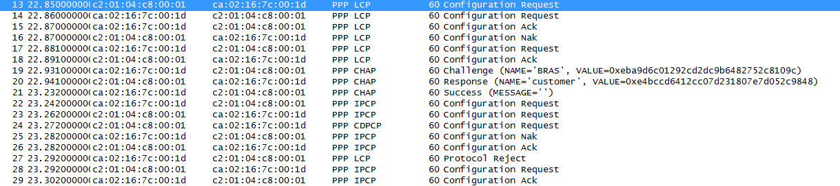
PPP LCP messages are explained in RFC1661 5.
– configure-request: open the connection and send configuration option (5.1)
– configure-ack: reply to the configuration request and acknowledge the configuration options that are acceptable (5.2)
– configure-nak: reply to the configuration request and deny the configuration options that are not acceptable (5.3)
– protocol-reject: reply to the configuration request and deny the configuration options that are not recognized (5.7)
PPP CHAP
– challenge: actively ask for authentication
– response: response to an authentication challenge
– success: if the value in response packet is the expected value
PPP LCP
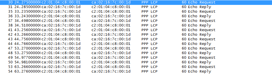
– echo request / echo reply: used to keep the link activated (Data Link Layer loopback mechanism); Useful as an aid in debugging, link quality determination, performance testing, and for numerous other functions.
Ping & MTU
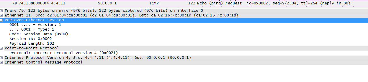 Overhead:
PPPoE: 6 bytes
PPP: 2 bytes
> MTU = 1500 – 6 – 2 = 1492
TCP: 40 bytes
> MSS = 1500 – 6 – 2 – 40 = 1452
Downloads
PPPoE lab config and captures
Ressources
https://supportforums.cisco.com/docs/DOC-8063
http://tools.ietf.org/html/rfc1661
http://tools.ietf.org/html/rfc1547
http://en.wikipedia.org/wiki/Broadband_Remote_Access_Server
http://www.ietf.org/rfc/rfc1994.txt
http://tools.ietf.org/html/rfc2516