
HSRP, Stateful NAT and BGP Default route advertisement
The purpose of this lab is to simulate a customer (AS65200) with two links connecting to an upstream service provider (AS65100).
The goal is to :
– Have a unique default gateway for the LAN
– Ensure NAT failover for the LAN
– Get a default route from the provider
Topology:
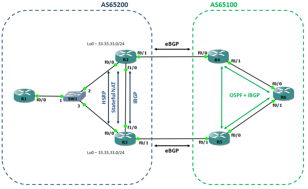
Technologies:
HSRP: Hot Standby Router Protocol is a First Hop Router Protocol (FHRP) that simulates a single virtual gateway (virtual IP address and virtual MAC address) for two or more physical routers. HSRP ensures the synchronization between the two routers by sending messages to the multicast address 224.0.0.102 (v2) or 224.0.0.2 (v1).
Stateful NAT: Network Address Translation provides a way to map multiple local IP addresses onto one or multiple external IP addresses. This mechanism was designed to slow down IP addresses exhaustion. NAT process maintains a NAT table on the router (show ip nat translations). Stateful NAT gives the possibility to synchronize two routers’ NAT tables. So when the main router goes down the translation keep working on the backup device.
BGP: Border Gateway Protocol is the current Internet routing protocol. It is highly tunable and highly scalable.
Step 1: Provider’s network
The provider’s network runs iBGP + OSPF to ensure full internal/external reachability.
R6 have a loopback interface that will be used for testing purpose
interface Loopback10
 ip address 66.66.66.66 255.255.255.0
R4 is the primary path:
router bgp 65100
 neighbor 24.24.24.2 remote-as 65200
 neighbor 24.24.24.2 default-originate
 neighbor 24.24.24.2 soft-reconfiguration inbound
R5 is the secondary path, therefore it is needed to make R5 announced routes less preferred:
router bgp 65100
 neighbor 35.35.35.3 remote-as 65200
 neighbor 35.35.35.3 default-originate
 neighbor 35.35.35.3 soft-reconfiguration inbound
 neighbor 35.35.35.3 route-map BACKUP out
!
route-map BACKUP permit 10
 set as-path prepend 65100 65100 65100
The default route is advertised to BGP peers with the following command: neighbor IP default-originate
Note that you can setup conditional default route advertisement with a route-map matching an upstream prefix: neighbor IP default-originate ROUTE-MAP
Step 2: BGP on CPEs
As you will notice, BGP default route is not affected by outbound filtering (as preprend), and consequently there are two different default routes in the customer network. This is not consistent, we need to keep only one.
To bypass this behavior, I set up an inbound route-map on R2, our main CPE:
router bgp 65200
 no synchronization
 bgp log-neighbor-changes
 redistribute connected
 redistribute static
 neighbor 23.23.23.3 remote-as 65200
 neighbor 23.23.23.3 next-hop-self
 neighbor 23.23.23.3 soft-reconfiguration inbound
 neighbor 24.24.24.4 remote-as 65100
 neighbor 24.24.24.4 soft-reconfiguration inbound
 neighbor 24.24.24.4 route-map LOCALPREF in
 no auto-summary
!
route-map LOCALPREF permit 10
 set local-preference 150
Both routers are running, we need to degrade R3’s route preference in order to keep R2 as main (route-map BACKUP):
router bgp 65200
 no synchronization
 bgp log-neighbor-changes
 redistribute connected
 redistribute static
 neighbor 23.23.23.2 remote-as 65200
 neighbor 23.23.23.2 next-hop-self
 neighbor 23.23.23.2 soft-reconfiguration inbound
 neighbor 35.35.35.5 remote-as 65100
 neighbor 35.35.35.5 soft-reconfiguration inbound
 neighbor 35.35.35.5 route-map BACKUP out
 no auto-summary
!
route-map BACKUP permit 10
 set as-path prepend 65200 65200 65200
There is also an iBGP peering between R2 and R3 to make sure that routing information is consistent in the AS.
Step 3: HSRP
In this HSRP configuration, I define:
– the VIP
– the priority (default on backup router)
– the name to identify the group
– the preemption on the main router
– the upstream interface tracking
R2:
R2#sh run int f0/0
interface FastEthernet0/0
 ip address 12.12.12.1 255.255.255.0
 ip nat inside
 ip virtual-reassembly
 duplex auto
 speed auto
 standby 10 ip 12.12.12.254
 standby 10 priority 200
 standby 10 preempt
 standby 10 name LAN-GW
 standby 10 track FastEthernet0/1

R2#sh standby bri
Interface   Grp Prio P State    Active          Standby         Virtual IP
Fa0/0       10  200  P Active   local           12.12.12.2      12.12.12.254
R3:
R3#sh run int f0/0
interface FastEthernet0/0
 ip address 12.12.12.2 255.255.255.0
 ip nat inside
 ip virtual-reassembly
 duplex auto
 speed auto
 standby 10 ip 12.12.12.254
 standby 10 name LAN-GW
 standby 10 track FastEthernet0/1

R3#sh standby bri
Interface   Grp Prio P State    Active          Standby         Virtual IP
Fa0/0       10  100    Standby  12.12.12.1      local           12.12.12.254
Step 4: Stateful NAT
In order to keep a common NAT interface on the routers, I define the following loopback interface:
interface Loopback0
 ip address 33.33.33.33 255.255.255.0
Then I define the NAT pool
ip nat pool POOL 33.33.33.33 33.33.33.33 netmask 255.255.255.0
I create an access-list to select the traffic to be NATed
ip access-list extended INTERNET
 permit ip 11.11.11.0 0.0.0.255 66.66.66.0 0.0.0.255
The translation command:
ip nat inside source list INTERNET pool POOL mapping-id 1 overload
Identify the inside and outside interfaces:
interface FastEthernet0/0
 ip nat inside
 ip virtual-reassembly
!
interface FastEthernet0/1
 ip nat outside
 ip virtual-reassembly
And finally the stateful NAT configuration:
– ip nat Stateful id 1 id is a locally significant number
– redundancy LAN-GW redundancy keyword is used to link stateful NAT to the HSRP instance
– mapping-id 1 must match on both routers, and in the translation command
R2:
ip nat Stateful id 1
  redundancy LAN-GW
   mapping-id 1
R3:
ip nat Stateful id 2
  redundancy LAN-GW
   mapping-id 1
Verify the SNAT configuration:
R2#sh ip snat distributed

Stateful NAT Connected Peers

SNAT: Mode IP-REDUNDANCY :: ACTIVE
    : State READY
    : Local Address 12.12.12.1
    : Local NAT id 1
    : Peer Address 12.12.12.2
    : Peer NAT id 2
    : Mapping List 1

R3#sh ip snat distributed

Stateful NAT Connected Peers

SNAT: Mode IP-REDUNDANCY :: STANDBY
    : State READY
    : Local Address 12.12.12.2
    : Local NAT id 2
    : Peer Address 12.12.12.1
    : Peer NAT id 1
    : Mapping List 1
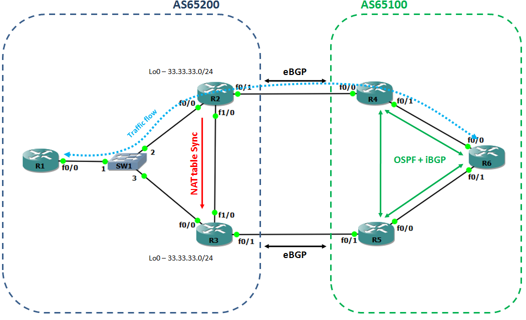
Verify NAT table sync:
R2#sh ip nat tr
Pro Inside global      Inside local       Outside local      Outside global
icmp 33.33.33.33:5     11.11.11.1:5       66.66.66.66:5      66.66.66.66:5
icmp 33.33.33.33:6     11.11.11.1:6       66.66.66.66:6      66.66.66.66:6

R3#sh ip nat tra
Pro Inside global      Inside local       Outside local      Outside global
icmp 33.33.33.33:5     11.11.11.1:5       66.66.66.66:5      66.66.66.66:5
icmp 33.33.33.33:6     11.11.11.1:6       66.66.66.66:6      66.66.66.66:6
Thank you for reading!