
HP Intelligent Resilient Framework
What is IRF ?
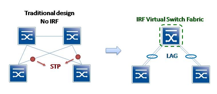
Those of you who are familiar with the Cisco Virtual Switching System (VSS) will easily understand what IRF is. HP Intelligent Resilient Framework has the same goal as VSS: simplify and improve switching systems. The goal is to reduce the complexity of L2 networks and to make them more efficient.
Originally, IRF was developped and used by H3C (Huawei-3COM). HP later acquired 3COM and gained access to this technology.
IRF take two or more devices to create one virtual device called the virtual switch fabric as exposed in the diagram.
Benefits of IRF
– Reduce management complexity
– Improved convergence time
– Simplified network design
– Better performances
– Better use of existing resources
– No more STP running, no redundancy protocol
– Improved scalability and resiliency
= Reduced operational costs
Supported platforms
IRF is available on different HP platforms:
– HP E4210G Switch Series
– HP E4800G Switch Series
– HP A5120 Switch Series
– HP A5500 Switch Series
– HP A5800 Switch Series
– HP A5820 Switch Series
– HP A7500 Switch Series
– HP A9500 Switch Series
– HP A10500 Switch Series
– HP A12500 Switch Series
Set up an IRF fabric
/!\ Be careful the order of configuration is very important !
Declare the domain number. Here we define Virtual Fabric Domain 10.
Declare the members of the IRF fabric: this is needed to identify each switch in the IRF fabric. This number is also used to renumber each switchports.
e.g.: member 1, line card 0, port 1 => Gi 1/0/1 , member 2, line card 0, port 1 => Gi 2/0/1
SW1
irf domain 10
irf member 1 renumber 1
save
reboot
SW2
irf domain 10
irf member 1 renumber 2
save
reboot
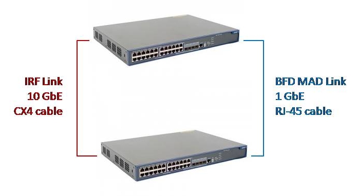
In this example the IRF link is defined between two 10GbE CX4 port.
Then I define the priority: it will determine whether the switch is master or slave. The master switch will be the one which is accessible and where you put the configuration. The configuration is then replicated to the slave. However you can still access the slave switch using irf switch-to X command.
MAC address persistent (Bridge MAC address is the MAC address of the elected master) is set to timer (Bridge MAC address is preserved for 6 minutes when the master leaves).
IRF auto update make the slave switch to automatically upgrade its OS if it is different from the master. Be careful with this setting in production environment 🙂
SW1
interface Ten-GigabitEthernet1/1/1
description ### IRF LINK ###
shutdown
quit

irf-port 1/1
port group interface Ten-GigabitEthernet 1/1/1

interface Ten-GigabitEthernet 1/1/1
undo shutdown
quit

irf-port-configuration active
irf member 1 priority 30
irf mac-address persistent timer
undo irf auto-update enable

save
reboot
SW2
interface Ten-GigabitEthernet2/1/2
description ### IRF LINK ###
shutdown
quit

irf-port 2/2
port group interface Ten-GigabitEthernet 2/1/2

interface Ten-GigabitEthernet 2/1/2
undo shutdown
quit

irf-port-configuration active
irf member 2 priority 20
irf mac-address persistent timer
undo irf auto-update enable

save
reboot
(plug cables)
Set up the Multi Active Detection (MAD). This mechanism is used to prevent all the IRF members to be active if the IRF link fails. There are different types of MAD: LACP MAD, ARP MAD, and BFD MAD. I chose to implement BFD MAD because, in the present scenario, this is the most easy to deploy and the most reliable (point to point link between the two switches). The BFD implementation is bit different: if there are two different IP addresses active, the BFD is active and it means that you are facing a split brain scenario. In a normal operation mode, the BFD should be down.
sysname CLUSTER10

vlan 2
description BFD-MAD-VLAN

interface GigabitEthernet 1/0/47
description ### BFD LINK ###
port access vlan 2
quit

interface GigabitEthernet 2/0/47
description ### BFD LINK ###
port access vlan 2
quit

interface Vlan-interface 2
mad bfd enable
mad ip address 192.168.10.1 255.255.255.0 member 1
mad ip address 192.168.10.2 255.255.255.0 member 2
quit
Last but not least, the troubleshooting commands:
display irf ?
  configuration  IRF configuration that will be valid after reboot
  topology       Topology information

display interface brief
Unset up an IRF fabric
Renumber the device (it is not contained in the configuration file).
Delete the config file.
Reboot the device.
> display device
 Slot 2
> irf member 2 renumber 1
> delete flash:/startup.cfg
Delete flash:/startup.cfg?[Y/N]:y
....
%Delete file flash:/startup.cfg...Done.
> reboot
 Start to check configuration with next startup configuration file, please wait.........DONE!
 This command will reboot the device. Current configuration will be lost, save current configuration? [Y/N]:n
 This command will reboot the device. Continue? [Y/N]:y
My opinion
IRF is a good technology on the paper. It is a bit tricky when you set up an IRF fabric for the first (and the second) time and could appear cumbersome.
However it offers interesting possibilities and clearly brings many advantages. The different tests I drove indicate that the virtual switch is reliable and offers good switch-over times.
Speaking about complexity, yes it reduces the global L2 network complexity, but you still need to know where you go in case of an IRF failure 😉
Links
HP FlexFabric: http://h30507.www3.hp.com/t5/HP-Networking/How-does-FlexFabric-fit-in-HP-s-data-center-networking-vision/ba-p/82943
http://h30507.www3.hp.com/t5/HP-Networking/Very-large-L2-networks-for-cloud-and-virtualization/ba-p/82213
http://www.youtube.com/watch?v=Zir7qJELlRM
IRF Guide: http://h20000.www2.hp.com/bc/docs/support/SupportManual/c02645768/c02645768.pdf