
MHSRP and MSTP lab
MHSRP
Multiple Hot Standby Router Protocol is not a new protocol, but a way of using Cisco HSRP to achieve pseudo load balancing. This is done by setting up multiple HSRP gateways and playing with their priorities.
MSTP
Multiple Spanning Tree Protocol (802.1s) is based on the Rapid Spanning Tree Protocol (802.1w). Most vendors implement per VLAN spanning tree protocols (R/PVST). But when there is a lot of VLANs it could create processing overhead on the switches and lower network performances. The aim of MSTP is to run a spanning tree instance for multiple VLANs that share similar characteristics and, thus, lower the total number of ST instances.
MST
Mono Spanning Tree or Common Spanning Tree (CST), a shared spanning tree
I think the topology speaks for itself:
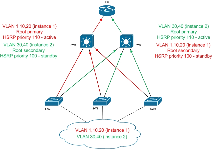
VLAN configuration on each switch
vlan 10
name MANAGEMENT
vlan 20
name MARKETING
vlan 30
name NETWORK
vlan 40
name SUPPORT
exit

# same configuration on SW2,SW3,SW4,SW5
VLAN interface + HSRP configuration
#SW1
interface Vlan10
ip address 10.10.10.2 255.255.255.0
standby 10 ip 10.10.10.1
standby 10 priority 110
standby 10 preempt
standby 10 authentication pass
interface Vlan20
ip address 20.20.20.2 255.255.255.0
standby 20 ip 20.20.20.1
standby 20 priority 110
standby 20 preempt
standby 20 authentication pass
interface Vlan30
ip address 30.30.30.2 255.255.255.0
standby 30 ip 30.30.30.1
standby 30 priority 100
standby 30 authentication pass
interface Vlan40
ip address 40.40.40.2 255.255.255.0
standby 40 ip 40.40.40.1
standby 40 priority 100
standby 40 authentication pass

#SW2
interface Vlan10
ip address 10.10.10.3 255.255.255.0
standby 10 ip 10.10.10.1
standby 10 priority 100
standby 10 authentication pass
interface Vlan20
ip address 20.20.20.3 255.255.255.0
standby 20 ip 20.20.20.1
standby 20 priority 100
standby 20 authentication pass
interface Vlan30
ip address 30.30.30.3 255.255.255.0
standby 30 ip 30.30.30.1
standby 30 priority 110
standby 30 preempt
standby 30 authentication pass
interface Vlan40
ip address 40.40.40.3 255.255.255.0
standby 40 ip 40.40.40.1
standby 40 priority 110
standby 40 preempt
standby 40 authentication pass
Trunks configuration:
#SW1
interface range e0/0 - 3
switchport
switchport trunk encapsulation dot1q
switchport mode trunk
switchport trunk allowed vlan 1,10,20,30,40
switchport nonegotiate

#SW2
interface range e0/0 - 3
switchport
switchport trunk encapsulation dot1q
switchport mode trunk
switchport trunk allowed vlan 1,10,20,30,40
switchport nonegotiate

Access switches configuration:
#SW3
interface range e0/0 - 1
switchport
switchport trunk encapsulation dot1q
switchport mode trunk
switchport trunk allowed vlan 1,10,20,30,40
switchport nonegotiate

#SW4
interface range e0/0 - 1
switchport
switchport trunk encapsulation dot1q
switchport mode trunk
switchport trunk allowed vlan 1,10,20,30,40
switchport nonegotiate

#SW5
interface range e0/0 - 1
switchport
switchport trunk encapsulation dot1q
switchport mode trunk
switchport trunk allowed vlan 1,10,20,30,40
switchport nonegotiate
MSTP configuration
#SW1
spanning-tree mst configuration
instance 1 vlan 1,10,20
instance 2 vlan 30,40
revision 1
name REGION1
exit
spanning-tree mst 1 root primary
spanning-tree mst 2 root secondary
spanning-tree mode mst

#SW2
spanning-tree mst configuration
instance 1 vlan 1,10,20
instance 2 vlan 30,40
revision 1
name REGION1
exit
spanning-tree mst 2 root primary
spanning-tree mst 1 root secondary
spanning-tree mode mst

#SW3
spanning-tree mst configuration
instance 1 vlan 1,10,20
instance 2 vlan 30,40
revision 1
name REGION1
exit
spanning-tree mode mst

#SW4
spanning-tree mst configuration
instance 1 vlan 1,10,20
instance 2 vlan 30,40
revision 1
name REGION1
exit
spanning-tree mode mst

#SW5
spanning-tree mst configuration
instance 1 vlan 1,10,20
instance 2 vlan 30,40
revision 1
name REGION1
exit
spanning-tree mode mst
Verification
SW1
SW1#show standby brief
P indicates configured to preempt.
|
Interface Grp Pri P State Active Standby Virtual IP
Vl10 10 110 Active local 10.10.10.3 10.10.10.1
Vl20 20 110 Active local 20.20.20.3 20.20.20.1
Vl30 30 100 Standby 30.30.30.3 local 30.30.30.1
Vl40 40 100 Standby 40.40.40.3 local 40.40.40.1

SW1#show spanning-tree mst

##### MST0 vlans mapped: 2-9,11-19,21-29,31-39,41-4094
Bridge address aabb.cc00.4600 priority 32768 (32768 sysid 0)
Root this switch for the CIST
Operational hello time 2 , forward delay 15, max age 20, txholdcount 6
Configured hello time 2 , forward delay 15, max age 20, max hops 20

Interface Role Sts Cost Prio.Nbr Type
---------------- ---- --- --------- -------- --------------------------------
Et0/0 Desg FWD 2000000 128.1 Shr
Et0/1 Desg FWD 2000000 128.2 Shr
Et0/2 Desg FWD 2000000 128.3 Shr
Et0/3 Desg FWD 2000000 128.4 Shr

##### MST1 vlans mapped: 1,10,20
Bridge address aabb.cc00.4600 priority 24577 (24576 sysid 1)
Root this switch for MST1

Interface Role Sts Cost Prio.Nbr Type
---------------- ---- --- --------- -------- --------------------------------
Et0/0 Desg FWD 2000000 128.1 Shr
Et0/1 Desg FWD 2000000 128.2 Shr
Et0/2 Desg FWD 2000000 128.3 Shr
Et0/3 Desg FWD 2000000 128.4 Shr

##### MST2 vlans mapped: 30,40
Bridge address aabb.cc00.4600 priority 28674 (28672 sysid 2)
Root address aabb.cc00.4a00 priority 24578 (24576 sysid 2)
port Et0/3 cost 2000000 rem hops 19

Interface Role Sts Cost Prio.Nbr Type
---------------- ---- --- --------- -------- --------------------------------
Et0/0 Desg FWD 2000000 128.1 Shr
Et0/1 Desg FWD 2000000 128.2 Shr
Et0/2 Desg FWD 2000000 128.3 Shr
Et0/3 Root FWD 2000000 128.4 Shr
SW2
P indicates configured to preempt.
|
Interface Grp Pri P State Active Standby Virtual IP
Vl10 10 100 Standby 10.10.10.2 local 10.10.10.1
Vl20 20 100 Standby 20.20.20.2 local 20.20.20.1
Vl30 30 110 Active local 30.30.30.2 30.30.30.1
Vl40 40 110 Active local 40.40.40.2 40.40.40.1

SW2#sh spanning-tree mst

##### MST0 vlans mapped: 2-9,11-19,21-29,31-39,41-4094
Bridge address aabb.cc00.4a00 priority 32768 (32768 sysid 0)
Root address aabb.cc00.4600 priority 32768 (32768 sysid 0)
port Et0/3 path cost 0
Regional Root address aabb.cc00.4600 priority 32768 (32768 sysid 0)
internal cost 2000000 rem hops 19
Operational hello time 2 , forward delay 15, max age 20, txholdcount 6
Configured hello time 2 , forward delay 15, max age 20, max hops 20

Interface Role Sts Cost Prio.Nbr Type
---------------- ---- --- --------- -------- --------------------------------
Et0/0 Altn BLK 2000000 128.1 Shr
Et0/1 Altn BLK 2000000 128.2 Shr
Et0/2 Altn BLK 2000000 128.3 Shr
Et0/3 Root FWD 2000000 128.4 Shr

##### MST1 vlans mapped: 1,10,20
Bridge address aabb.cc00.4a00 priority 28673 (28672 sysid 1)
Root address aabb.cc00.4600 priority 24577 (24576 sysid 1)
port Et0/3 cost 2000000 rem hops 19

Interface Role Sts Cost Prio.Nbr Type
---------------- ---- --- --------- -------- --------------------------------
Et0/0 Desg FWD 2000000 128.1 Shr
Et0/1 Desg FWD 2000000 128.2 Shr
Et0/2 Desg FWD 2000000 128.3 Shr
Et0/3 Root FWD 2000000 128.4 Shr

##### MST2 vlans mapped: 30,40
Bridge address aabb.cc00.4a00 priority 24578 (24576 sysid 2)
Root this switch for MST2

Interface Role Sts Cost Prio.Nbr Type
---------------- ---- --- --------- -------- --------------------------------
Et0/0 Desg FWD 2000000 128.1 Shr
Et0/1 Desg FWD 2000000 128.2 Shr
Et0/2 Desg FWD 2000000 128.3 Shr
Et0/3 Desg FWD 2000000 128.4 Shr
On access switches you can check the pseudo load balancing setup
##### MST0 vlans mapped: 2-9,11-19,21-29,31-39,41-4094
Bridge address aabb.cc00.4700 priority 32768 (32768 sysid 0)
Root address aabb.cc00.4600 priority 32768 (32768 sysid 0)
port Et0/0 path cost 0
Regional Root address aabb.cc00.4600 priority 32768 (32768 sysid 0)
internal cost 2000000 rem hops 19
Operational hello time 2 , forward delay 15, max age 20, txholdcount 6
Configured hello time 2 , forward delay 15, max age 20, max hops 20

Interface Role Sts Cost Prio.Nbr Type
---------------- ---- --- --------- -------- --------------------------------
Et0/0 Root FWD 2000000 128.1 Shr
Et0/1 Desg FWD 2000000 128.2 Shr

##### MST1 vlans mapped: 1,10,20
Bridge address aabb.cc00.4700 priority 32769 (32768 sysid 1)
Root address aabb.cc00.4600 priority 24577 (24576 sysid 1)
port Et0/0 cost 2000000 rem hops 19

Interface Role Sts Cost Prio.Nbr Type
---------------- ---- --- --------- -------- --------------------------------
Et0/0 Root FWD 2000000 128.1 Shr
Et0/1 Altn BLK 2000000 128.2 Shr

##### MST2 vlans mapped: 30,40
Bridge address aabb.cc00.4700 priority 32770 (32768 sysid 2)
Root address aabb.cc00.4a00 priority 24578 (24576 sysid 2)
port Et0/1 cost 2000000 rem hops 19

Interface Role Sts Cost Prio.Nbr Type
---------------- ---- --- --------- -------- --------------------------------
Et0/0 Altn BLK 2000000 128.1 Shr
Et0/1 Root FWD 2000000 128.2 Shr
RIP setup to propagate networks between SW1 – SW2 – R8
(there is an offset list in order to higher the metric of the routes for which the switch is not the gateway, though avoiding suboptimal routing)
#R8
router rip
version 2
network 1.0.0.0
network 2.0.0.0
no auto-summary

#SW1
router rip
version 2
network 2.0.0.0
network 10.0.0.0
network 20.0.0.0
network 30.0.0.0
network 40.0.0.0
no auto-summary
offset-list NON-ROOT-VLANS out 10

ip access-list standard NON-ROOT-VLANS
permit 30.30.30.0 255.255.255.0
permit 40.40.40.0 255.255.255.0

#SW2
router rip
version 2
network 1.0.0.0
network 10.0.0.0
network 20.0.0.0
network 30.0.0.0
network 40.0.0.0
no auto-summary
offset-list NON-ROOT-VLANS out 10

ip access-list standard NON-ROOT-VLANS
permit 10.10.10.0 255.255.255.0
permit 20.20.20.0 255.255.255.0